Build a replacement power switch assembly for the older Kenwood stereo receivers which used the NLA power switch mounted on the rear of the speaker selector switch
Click small picture to enlarge. ClicPic Gallery Software. | ||||||||||||||||||||||||


Keeping older equipment looking original when parts are no longer available can be challenging. The stereo receiver in question here is a Kenwood model KR-5030. It uses a power switch mounted on the rear of the speaker select switch. The switch is a rotary design, and the shaft activates a cam inside the power switch which pushes the AC contacts together, turning on the unit. The original power switch (shown above in photo #2), Kenwood part # S29-1131-00 is apparently no longer available.
What can be done if this part needs replacement? Easiest thing to do is put an in-line switch in the AC cord and place a permanent jumper across the original power switch. Another method would be to find a convenient spot on the receiver to mount a toggle switch. Not exactly keeping the unit very close to original if the audio buff so requires it.
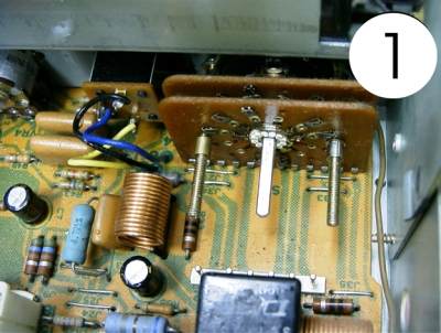
Enter here is little project. I rigged this up for a customer in order to keep the unit looking and working as it was designed, at least from the outside everything is the same. Photo #1 shows the rear of the speaker select switch after the original power switch was removed. Notice the little spacers (up against the surface of the switch) on the threaded rods. These spacers need to be left in there. As mentioned, photo #2 shows the original power switch. In Photo #3, you see the new switch mounted on 3/32 thick aluminum plate. I used a common everyday micro-switch, rated 15 Amp 250V AC. The micro switch needs to have the metal lever bar to activate the button and also needs to have a Normally Closed (NC) and a common contact.
Photo #4 shows the various parts used to build the assembly. The cam was removed from the original power switch and the 5/16" hole drilled in the center of the plate matches the shoulder size on the cam, therefore the cam fits into the hole and rotates freely. The micro-switch needs to be mounted carefully as to have it's button pushed in when the cam rotates and makes contact with it. It is important for this to be precise for the switch to function properly. Photo # 5 is the layout and measurements I used to make the aluminum plate. You can use it as a basic template although you may have a slightly different size switch, etc.
Photos # 6, 7, and 8 show the new switch assembly mounted on the speaker select switch. Notice in photo #7 that a collar has been added to the shaft to block the cam from popping out of position. I happened to have some of these collars on hand so I don't know where one could be purchased.
After installation, take a continuity tester and verify that the switch does not make contact in the OFF position and does make good contact when the speaker switch is rotated to any of the other positions. Solder the power wires to the switch. DONE.